|


|

|
|
|
The Manual 3-spd Steering Column
Explored |
|
 |
|
This page is a
collection of photos and observations I made while disassembling
a pair of manual three-speed (a.k.a. '3-on-the-tree') steering
columns. The photos contained will probably eventually be
incorporated into a "How To Rebuild" tutorial, but in the
meantime I decided to post these pictures just for visual
reference. |
|
Both
of the steering columns reviewed in this article have been
removed from the vehicles.
Start by removing the steering wheel with an appropriate puller,
and then sliding the main shaft out the bottom end of the
column. There will be a spring under the steering wheel holding
the upper column shaft bushing into the upper bearing...don't
lose the spring or bushing. Also, remove the spring-loaded horn
contact from the turn signal switch so it doesn't fall out and
get lost. Next, remove the turn signal stalk, then the shift
handle (by driving out the retaining pin) and finally the three
Phillips-head screws holding the turn signal retaining plate
(Fig. 01).
Next, you'll need to remove the turn signal switch. Because the
wiring is snaked up through the column, and the plastic harness
connectors are too large to pull through, you'll have to remove
the connectors. You do this by using the yellow-handled tool
(Fig. 02) to release the small prongs for each wire and remove
all wires from the connector. But first you need to make a
careful inspection (and take some notes) about the proper
orientation of the wires, so they can be replaced in their
respective positions during reassembly. Pull the turn signal
switch up and out of the column.
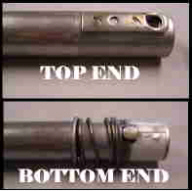
Next, use a 7/16" socket to remove the two nuts holding the turn
signal housing from the column housing. When you go to lift the
turn housing away from the column housing, be sure you don't
lose the two bolts. The heads of these two bolts are just barely
hooked into holes in the end of the column housing, as shown in
Fig. 04. Also shown in Fig. 04 and marked with a yellow arrow is
the end of the shift tube, as it extends up through the shift
collar.
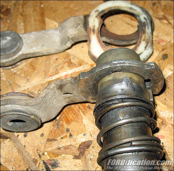
Next, make a schematic of how the shifter arms at the base of
the column are arranged, and then you can slide the shift collar
and shift tube out from the main column housing. (The shift tube
is actually separate from the shift collar, so it's possible
it'll slide off the tube first, and then you can grab the tube
and pull it out.) This in turn will release the two shifter arms
at the base of the column. You'll notice that there is a thin
plastic thrust washer on each side of the shifter arm pack, as
well as a thicker plastic spacer between the two shifter arms.
Pull the two shifter arms out of the column, along with the two
thrust washers, and then rotate the thick spacer around 90-degrees so
that it can be removed from the main column housing. The spacer is flat on two sides to allow for easy
installation/removal and must be spun for clearance to remove
(Fig. 8). |

Fig. 01 - I've removed the three screws holding the turn
signal switch.

Fig. 02 - Use the yellow-handled tool to release the column
wiring from the connectors.

Fig. 03 - Remove these two nuts and remove the column
spacer.
|
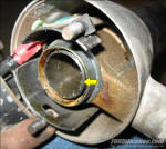
Fig. 04 - Shown are the two bolts holding the turn signal
housing to the main housing. The yellow arrow shows the end of
the shift tube. |
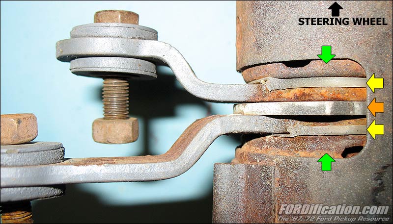
 Fig. 05
-
Here is a close-up of the shift arm configuration. The
green arrows indicate the welded-in housing spacers,
between which everything else fits and are not
removable. The yellow arrows point to the thin plastic
thrust washers on each end of the shifter arm pack. Note the lip
on each of the thrust washers that grip each respective
shifter arm. The orange arrow points to the thick
plastic spacer between the two shifter arms. Once the
shift tube is slid out the top of the column, these will
be loose, so remove them carefully, paying attention to
the proper orientation of the spacer and each thrust
washer. Fig. 05
-
Here is a close-up of the shift arm configuration. The
green arrows indicate the welded-in housing spacers,
between which everything else fits and are not
removable. The yellow arrows point to the thin plastic
thrust washers on each end of the shifter arm pack. Note the lip
on each of the thrust washers that grip each respective
shifter arm. The orange arrow points to the thick
plastic spacer between the two shifter arms. Once the
shift tube is slid out the top of the column, these will
be loose, so remove them carefully, paying attention to
the proper orientation of the spacer and each thrust
washer. |
|
 |
|
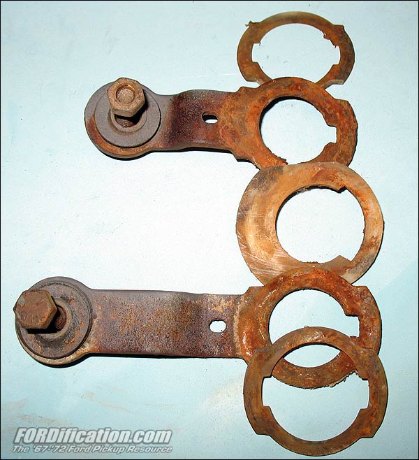
Fig. 06 - Here are the shifter arms,
thrust washers and spacer in the correct orientation. |
|
|
 |
|
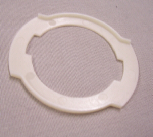
Fig. 07 - Here are the two thrust
washers. I have one in place on a shifter arm,
and you can see how the lip of each shim
fits snugly over the end of the shifter arm. |
|
|
 |
|
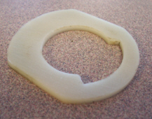
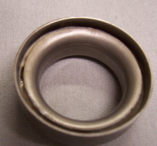
Fig. 08 - Here is the thick spacer.
I'm holding it as it would be oriented
inside the column housing. To install, you
turn it 90 degrees clockwise, insert it, and
then spin it back 90 degrees. |
|
|
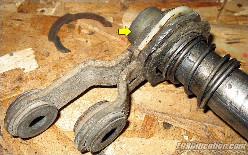
Here
is a shot of the setup on a different column, showing the
shifter arm pack on the end of the shift tube. You can see that
the bottom thrust washer is broken. The yellow arrow points to a
plastic sleeve which is slid over the end of the shift tube.
With all the plastic pieces in this setup, you can definitely
begin to see how these wearing out will cause the shifter arms
to become loose and unstable, which could cause difficulty in
shifting and possible binding. The shifter arms are held
laterally stationary by the column housing spacers, and the
shift tube slides back and forth through the arms, engaging each
one with a tab mounted onto the end of the shifter tube. |

Fig. 09 |
|
This
is a close-up of the tab on the shifter tube that actuates the
shifter arms. The spring holds the tube engaged
with the short shifter arm, which is the 2-3 (2nd-gear/3rd-gear)
arm. When the shifter handle is pulled toward the driver, it
pivots in the shift collar and pushes down on the shifter tube,
over-riding the spring. The tab will disengage from the 2-3 arm
and engage the longer R-1 (Reverse/1st-gear) arm. You can also
see the plastic sleeve on the end of the tube. |

Fig.
10 |
|
In
this picture, I've slid the short 2-3 arm back on the shift tube
without the plastic shim. You can see how the metal tab on the
shifter arm engages the arm. When a driver pulls the shift lever
towards himself to shift into Reverse or 1st gears, the column
is pushed down through this 2-3 arm (and the thick plastic
spacer) enough that the metal tab no longer engages it, but
instead engages into the longer R-1 arm beneath it. At this
point the spring is almost fully compressed. |

Fig.
11 |
|
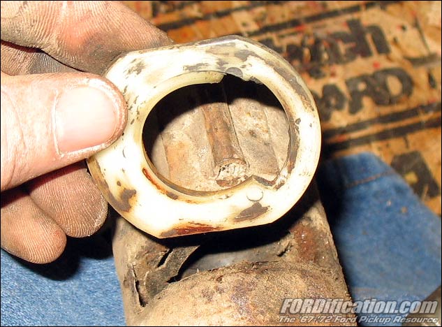
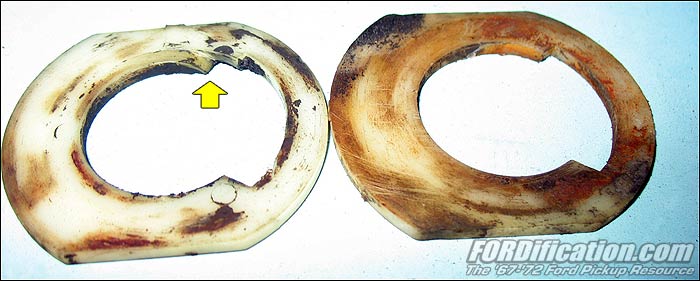
The
yellow arrow in Fig. 16 is pointing to a section of the thick
plastic spacer. See where it's worn into a 'ramp'? Compare it to
the other and you can see it's not supposed to be like that.
This would have been caused by the shifter lever not being
pushed all the way down when shifting into third gear, causing
the spot-welded tab to 'catch' the edge when shifting from
second to third gear. |

Fig.
12 |
|
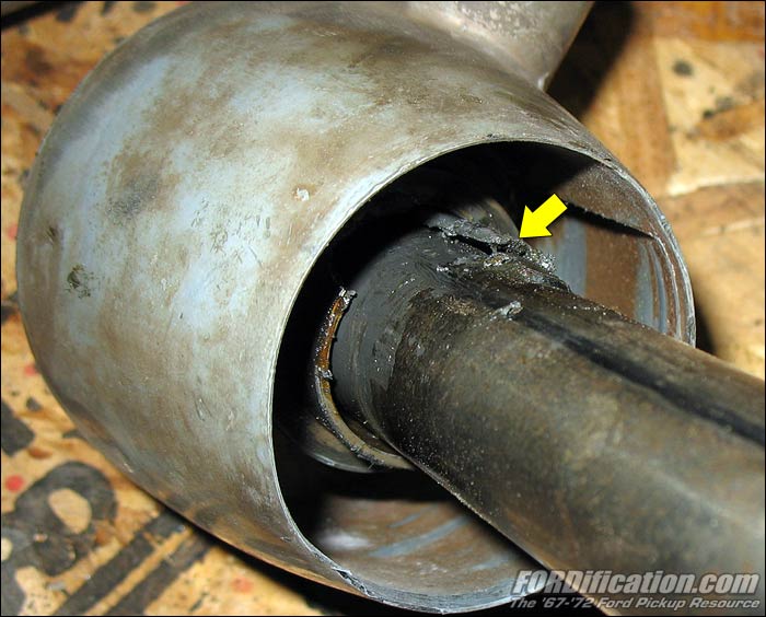
OK,
let's head back up to the business-end of the column. The other
end of the shifter tube slides into the shift collar. There is a
metal tab welded onto the top end of the tube that engages it to
the collar, and as a driver is shifting, the tube slides up and
down in the collar. In Fig. 12, however, you can see how the
shift tube tab has come loose...it's no longer attached to the
tube. However, because of the semi-tight fit, it still
shifted...although it was very sloppy...and it was a major PIA
to slide the tube out of the collar. I ended up having to drive
it out from the top. |

Fig.
13 |
|
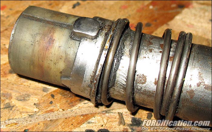
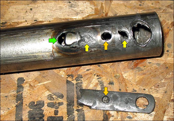
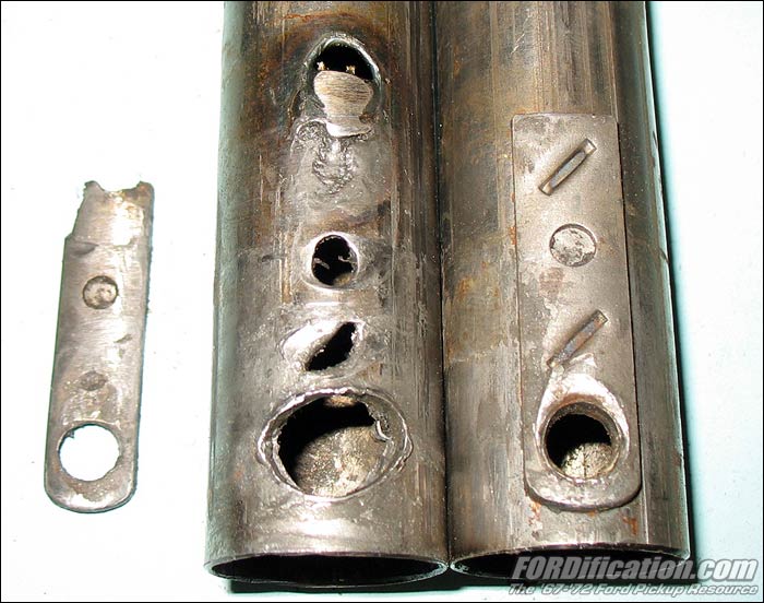
...and here's the carnage. The hole in the right side of the tab
is supposed to line up with the hole in the end of the tube.
It's this hole that the shifter lever fits into to move the
shift tube up and down. Therefore, the tab not only keeps the
tube engaged with the shift collar, but provides some extra
support for the thin shift tube, to minimize damage from the
shift lever. You can see how rounded-out the hole in the shift
tube is, since the tab was no longer reinforcing the hole. The
tab has a very short tang on the bottom side which fits into the
pilot hole (orange arrow) and is then spot-welded to the tube
(yellow arrows). However, when the two factory spot-welds broke,
apparently the previous owner decided to weld it back in place
at the end of the tab, but in doing so completely burned through
the tube (green arrow). And the weld wasn't any good anyway,
since it obviously broke again afterwards. |

Fig.
14 |
|
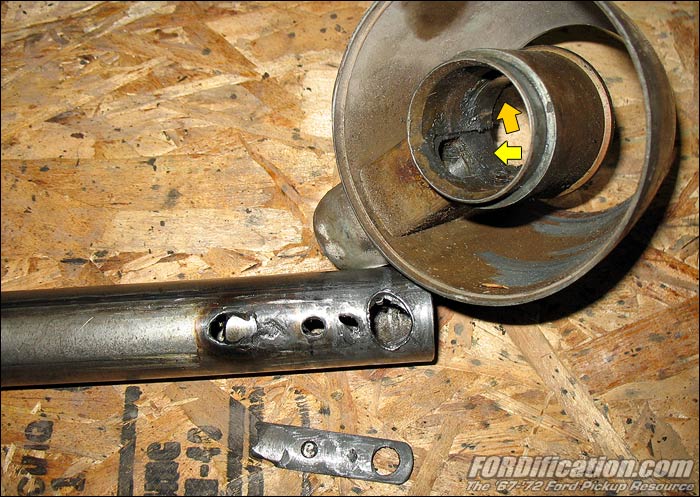
The
yellow arrow in this shot is pointing to the groove in the shift
collar that the tab is supposed to ride in. You can also see the
hole through which the shifter lever extends to engage the
shifter tube. The tube rides up and down in the close confines
of the collar as indicated by the orange arrow. This area needs
to be lubricated for smooth operation of the shift tube. |

Fig.
15 |
|
Here's a comparison shot of the bad shift tube and a good one,
with the tab still attached with the factory spot-welds. |

Fig.
16 |
|
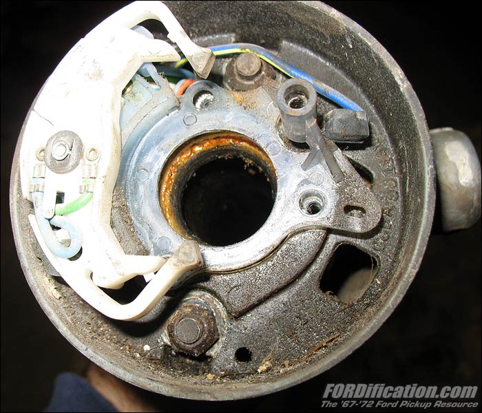
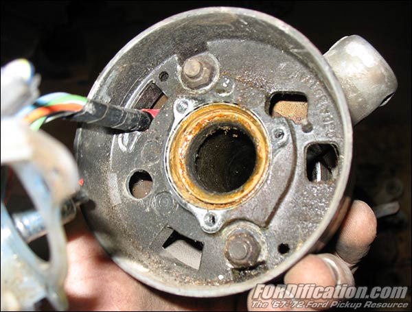
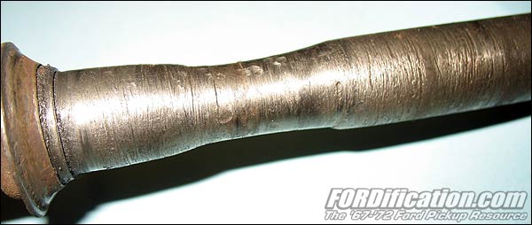
It
was very obvious to me that both of these 3-spd. columns had
been disassembled by previous owners. This shot of a VERY worn
column shaft couldn't have happened with a 3-spd column, since
the shaft is inside the shift tube, and the tube would have worn
out first. This could only have come from a 4-spd
manual-steering truck that didn't have a shifter tube, and would
have been caused from bad front cab mounts which let the cab
sink down in front, putting pressure on the bearing. The bearing
would have eventually worn out, and then the shaft would have
started to ride on the bearing housing, causing this wear. |

Fig.
17 |
|
|
|
Replacing the Upper Column bearing |
|
I
decided to try pressing out the upper column bearing, just for the
practice. I figured it could be easily pressed out with a large
C-clamp, but after spending nearly 30 minutes unsuccessfully looking
for mine in the shop, I decided to just use the bench vise, which
worked beautifully. Just be ready to catch everything, because once
the bearing pops out, everything will hit the floor. I actually
ended up denting this housing when it landed on it's side, but
fortunately this was just a trial run and this particular piece just
gave it's life for the educational aspect. |
|

Fig.
18 |
|
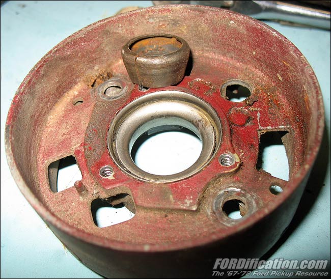
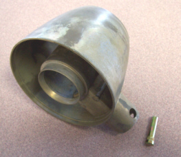
Here is the turn signal housing, with the pressed-in
bearing, along with the steel column bushing. |
|
|

Fig.
19 |
|
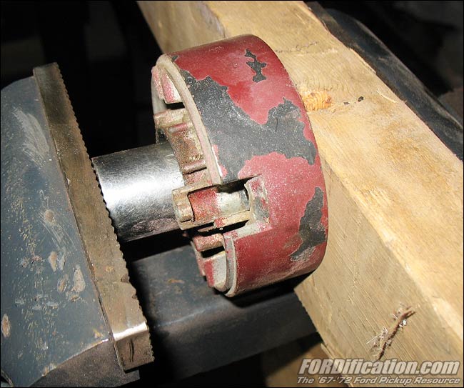
Clamped this up in the bench vise, which worked great.
The 2x4 was to keep the jaws from marring the housing. |
|
|

Fig. 20 |
|
...and here's the newly-removed bearing. |
|
Exploded-view Schematics
(from
the Ford Master Parts catalog) |
|
 |
|
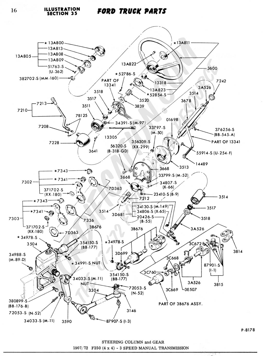
Steering Column
and
Gear
(with 3-spd manual transmission)
1966-1972 F250 (4x4)
1024
x 1386, 125K |
|
|
 |
|
Steering Column,
Gear and Wheel
(3-spd and automatic)
1965-1972 F100/F350 (4x2)
1967 F350 (4x2)
1024 x 1359,
194K |
|
|
|
PARTS NECESSARY FOR REBUILDING
SOURCES:
Macs Auto Parts,
EarlyFord.com,
Dennis-Carpenter.com,
CarolinaClassics.com |
 |
Column Shift Arm Spacer
(Fig. 8 above, orange arrow) |
'65-'71 |
C9TZ-7336-A |
$3.95 ea |
|
'72-'79 |
D2TZ-7336-A |
$3.95 ea. |
 |
Column Gear Shift Arm Thrust Washers
(Fig. 8
above, yellow arrows)
(2 per truck) |
1965-79 F100/250, Bronco |
C5TZ-7D363-B |
$2.00 ea. |
 |
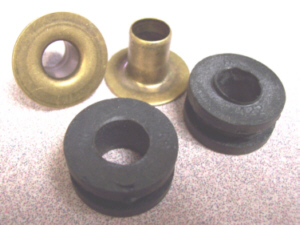
Gear Shift Selector Arm Bushing
& Insulator Kit
(located on the ends of each of the two shifter arms, as seen in
Fig. 8) |
'65-'72 F100/250
|
C5TZ-7343-A |
$16.00 kit |
 |
Shift Tube |
'61-'77 |
|
$50 - $60.00 |
 |
Upper and Lower column
bearings |
'64-'72 |
|
$6.00 |
 |
Upper bearing sleeve |
'53-'77 |
B1AZ-3518-A |
$4.50 |
 |
Shift collar for standard shift |
'61-'77 |
|
$38.00 |
 |
Steering column tube flange
(picture courtesy of
Macs Auto Parts) |
'66-'72 |
C5DZ-3511-A |
$29.95 |
(pictures courtesy of
CarolinaClassics.com
unless otherwise noted).
CarolinaClassics also has a complete column rebuilding service.
I've
been unable to locate a source for the plastic sleeve located at
the base of the shifter tube (as seen in Fig. 10). In fact, it
doesn't even show up on the exploded-view diagrams above. If you
have any info on this piece, please
e-mail me. |
|
 |

Want to link to
this site? Please save this banner to your hard drive to place on your
webpage.
The correct link to use is
http://www.fordification.com
|